


Electronic circuits provide a path for current to flow and are used to power all of our electrical devices. The two most fundamental types of circuits are series circuits and parallel circuits. Understanding how these circuits work and differ is essential for anyone involved in electronics or electrical engineering.
Series Circuits: One Path for Current
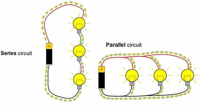
In a series circuit, there is only one path for current to flow. All components in a series circuit are connected end-to-end, so current must pass through each component before moving on to the next. If any component is disconnected or fails in a series circuit, current stops flowing altogether.
Series circuits provide the same amount of current to each component, so each component must be capable of handling the full current load. The total voltage drop in a series circuit is equal to the sum of the voltage drops of each individual component. Series circuits are used when the load requires the full source voltage, as in welding equipment or battery-powered locomotives.
As technology pioneer Gordon Moore said, “Series circuit means the current has to go through each thing, one after the other. There’s only one path, so if anything breaks, the circuit is open.”
Parallel Circuits: Multiple Paths
Unlike series circuits, parallel circuits provide multiple paths for current to flow. In a parallel circuit, each component has its own individual path to the voltage source. Parallel circuits are more complex but also more practical for most applications.
In a parallel circuit, the voltage drop is the same across each branch, but the current divides and flows through each branch separately. The total current flowing out of the source adds up to the sum of currents flowing through each branch. Parallel circuits are commonly used in households to power lighting and appliances at the same standard voltage levels.
According to American scientist Robert Noyce, who co-invented the integrated circuit, “Parallel circuits mean you have a separate path for each thing, so if one thing breaks, the current can still get through to the other things that are still working.”
Calculating Current, Voltage, and Resistance
To analyze circuits, we need to understand how current, voltage, and resistance relate for series and parallel connections. In a series circuit, the current is the same in all parts of the circuit, while voltage divides up and resistance adds together. In a parallel circuit, the voltage is the same across all branches, while current divides up and resistance depends on the number of branches.
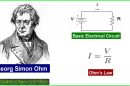
We can use Ohm’s law (V=IR) and the formulas for series and parallel resistances to calculate the voltage, current, and resistance in any type of circuit. Resistance in series is calculated as Rtotal=R1+R2+R3, while resistance in parallel is 1/Rtotal=1/R1+1/R2+1/R3. With some practice, these calculations will become second nature when designing and troubleshooting circuits.
In summary, series and parallel circuits follow different rules for how voltage, current, and resistance are distributed. A series circuit has only one path for current with the same current in all parts, while a parallel circuit has multiple paths with the current dividing in each branch. With an understanding of how these fundamental circuits work, you’ll be able to tackle more complex circuit designs and analyses.