


An oscilloscope is a vital tool for any electronics enthusiast or engineer, allowing for visual analysis of electrical signals. While commercial oscilloscopes can be expensive, constructing your own DIY oscilloscope can be an affordable and rewarding endeavor. As Thomas Edison once famously stated, “To invent, you need a good imagination and a pile of junk.” In this guide, we will explore the steps involved in building your own oscilloscope, diving into the necessary components, the construction process, and the programming required to bring it to life.
Understanding Oscilloscopes: The Basics
Before delving into the construction process, let’s familiarize ourselves with the fundamentals of oscilloscopes. An oscilloscope is a test instrument used to display and analyze the waveform of electronic signals. It allows you to observe voltage signals over time, providing insight into the behavior and characteristics of circuits.
Oscilloscopes typically consist of a display screen, vertical and horizontal controls, and input channels. The vertical controls adjust the vertical scale and position of the waveform, while the horizontal controls determine the time base and position of the waveform.
The input channels are where the electrical signals are connected, and they can be adjusted to accommodate different voltage ranges. Additionally, oscilloscopes often come with various triggering options to help capture specific signal events.
Components: What You’ll Need
To build your DIY oscilloscope, you will need several key components. Here’s a list of the essential items:
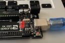
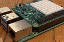
- Microcontroller: The brain of your oscilloscope, responsible for processing and displaying the waveform. Arduino is a popular choice for DIY oscilloscope projects due to its versatility and community support.
- Display: A graphical display, such as an LCD or OLED, to visualize the waveform. The size and resolution of the display will impact the level of detail you can observe.
- Analog-to-Digital Converter (ADC): Converts the analog voltage signals from the input channels into digital data that the microcontroller can process.
- Input Circuitry: This includes signal conditioning components such as amplifiers, attenuators, and voltage dividers to adapt the incoming signals to the voltage range of the ADC.
- Probes: The connectors used to connect your circuit to the oscilloscope’s input channels. Probes ensure proper signal transmission and prevent interference.
- Power Supply: A stable power source to provide the necessary voltage and current for the microcontroller, display, and other components.
Building Your DIY Oscilloscope: The Construction Process
Now that you have an overview of the components, let’s dive into the construction process. Keep in mind that the specific steps may vary depending on the chosen microcontroller and display, so refer to the respective documentation for detailed instructions. However, the general process includes the following steps:
- Set up the microcontroller: Install the necessary development environment and libraries for programming the microcontroller. Connect the microcontroller to your computer for programming.
- Build the input circuitry: Construct the signal conditioning circuitry to adapt the incoming signals to the voltage range of the ADC. This may involve building amplifiers, attenuators, or voltage dividers depending on your specific requirements.
- Connect the display: Wire the display to the microcontroller, ensuring proper pin connections and compatibility. This may involve soldering or using jumper wires depending on the chosen display module.
- Program the microcontroller: Write the code to control the ADC, display, and other necessary functionalities. The code should include functions to read analog input signals, convert them to digital data, and display the waveform on the screen.
- Assemble and test: Once all the components are connected and programmed, assemble the oscilloscope and test its functionality. Check for proper waveform display, accuracy, and response time.
Expanding the Possibilities: Advanced Features and Functionality
With the basic DIY oscilloscope complete, there are several possibilities for expansion and improvement. Here are a few ideas to enhance your oscilloscope:
- Multiple Input Channels: Add more input channels to simultaneously monitor multiple signals.
- Adjustable Voltage Ranges: Incorporate switches or digital potentiometers to allow for adjustable voltage ranges on the input channels.
- Triggering Options: Implement various triggering options, such as edge triggering or level triggering, to capture specific events in the waveform.
- Data Logging and Analysis: Include functionality to log and analyze waveform data, enabling advanced signal processing and data visualization.
- Signal Generator: Integrate a signal generator module to produce test signals for calibration and troubleshooting purposes.
In Conclusion: Unlocking the Potential of DIY Oscilloscopes
Building your own DIY oscilloscope is a rewarding experience that combines electronics, programming, and practical applications. As you construct and refine your oscilloscope, you’ll gain a deeper understanding of signal analysis and the inner workings of electronic circuits. Remember the words of Albert Einstein, “The only source of knowledge is experience.” By embarking on this DIY project, you are immersing yourself in the experience of exploring electronics and unleashing the full potential of an oscilloscope.